
FROM AN IDEA TO A REQUIREMENT
What to specify for this attachment
Use these decisions to turn the work requirement into a model and configuration enquiry.
| Decision | Why it matters | Information to provide |
|---|---|---|
| Required movement | Changing a tool, tilting it and rotating it are separate functions. | The intended tool and movement, with the required angle/clearance. |
| Upper and lower interfaces | A model name or machine class does not define the complete connection. | Machine identity, pin diameter, centres, inside width and existing tool interface. |
| Hydraulic connections | Locking, rotation or tilt may have separate requirements from the connected tool. | Available circuits, flow, pressure, return and required hose arrangement. |
| Installation information | The final arrangement must retain the applicable locking and operating information. | Current mounting drawing, full model/suffix and the intended attachment. |
View the supplied catalogue drawing and original technical page
Supplier-provided catalogue reference · P03 physical page 10. Check the exact model header, configuration and source version. This excerpt is not a substitute for the current approved installation drawing or a model-specific test report.
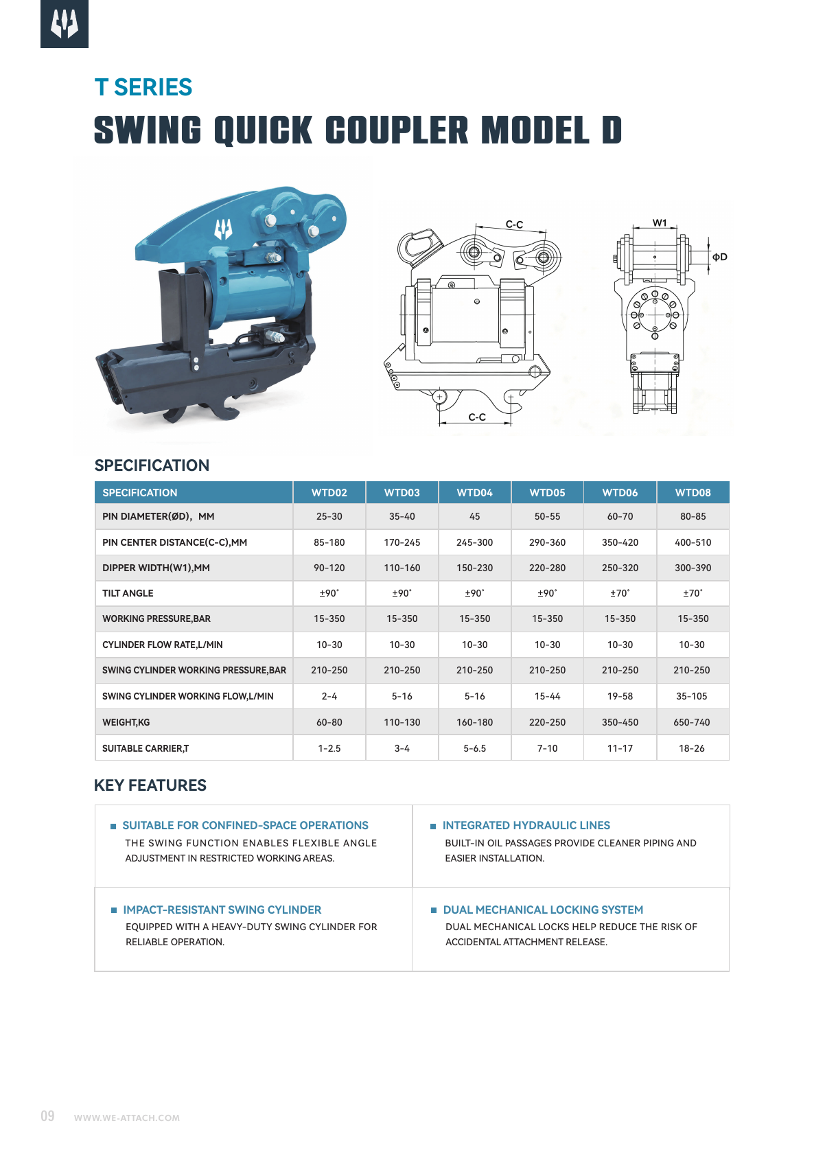
Catalogue specifications and source
| Field | Catalogue reference | Source physical page |
|---|---|---|
| Model | WTD04 | P03 · p.10 ↗ |
| PIN DIAMETER(ØD),MM | 45 | P03 · p.10 ↗ |
| PIN CENTER DISTANCE(C-C),MM | 245-300 | P03 · p.10 ↗ |
| DIPPER WIDTH(W1),MM | 150-230 | P03 · p.10 ↗ |
| TILT ANGLE | ±90° | P03 · p.10 ↗ |
| WORKING PRESSURE,BAR | 15-350 | P03 · p.10 ↗ |
| CYLINDER FLOW RATE,L/MIN | 10-30 | P03 · p.10 ↗ |
| SWING CYLINDER WORKING PRESSURE,BAR | 210-250 | P03 · p.10 ↗ |
| SWING CYLINDER WORKING FLOW,L/MIN | 5-16 | P03 · p.10 ↗ |
| WEIGHT,KG | 160-180 | P03 · p.10 ↗ |
| SUITABLE CARRIER,T | 5-6.5 | P03 · p.10 ↗ |
Drawing letters such as A/B refer to the original drawing keys; verify dimensions and units with the current model drawing.
Purpose and task
WTD04 is the tilting D coupler reference for angled excavation and finishing. Tilt a connected attachment for slopes, trenches and angled work with the WTD D-type coupler.
How this helps your buying decision
The catalogue lists ±90°. Check that movement with the mounting, tool geometry and its separate swing circuit. Compare WTD04 with WTD05 using each complete model row. The listed geometry and any carrier reference are starting points, not approval that the models are interchangeable. Keep any suffix, slash or configuration designation with the order.
Compare WTD04 with WTD03 as separate source-listed configurations. For WEIGHT,KG, the listed values are 160-180 (WTD04) and 110-130 (WTD03). For SUITABLE CARRIER,T, the listed values are 5-6.5 (WTD04) and 3-4 (WTD03). Keep units, mounting position, circuit labels and document conditions with each value. Similar model numbers or overlapping carrier references do not prove fitment, interchangeability or a better result for your task.
Model and configuration
The model-specific catalogue row states PIN DIAMETER(ØD),MM: 45; PIN CENTER DISTANCE(C-C),MM: 245-300; DIPPER WIDTH(W1),MM: 150-230; TILT ANGLE: ±90°; WORKING PRESSURE,BAR: 15-350; CYLINDER FLOW RATE,L/MIN: 10-30; SWING CYLINDER WORKING PRESSURE,BAR: 210-250; SWING CYLINDER WORKING FLOW,L/MIN: 5-16; WEIGHT,KG: 160-180; SUITABLE CARRIER,T: 5-6.5. Retain the original dimension keys, circuit names, units and source physical page with these values.
Machine and interface review
Measure the actual machine-side and tool-side pin diameters, centre distances and inside widths. Check installation space, tool movement and interference against both interface drawings. Keep upper and lower connections separate even when they look similar.
Hydraulic, control and installation conditions
The source lists WORKING PRESSURE,BAR: 15-350; CYLINDER FLOW RATE,L/MIN: 10-30; SWING CYLINDER WORKING PRESSURE,BAR: 210-250; SWING CYLINDER WORKING FLOW,L/MIN: 5-16. Keep each pressure and flow value with its printed circuit label. Confirm controls, valves, hose/coupling and return requirements for the ordered assembly; connected powered tools have their own hydraulic demands. The swing-cylinder values are separate from coupler actuation. Keep the signed angle and degree symbol as printed rather than treating one number as total travel.
Structure and differences
The WTD arrangement places a tilt mechanism between the upper excavator mounting and the lower tool connection. The supplied material identifies built-in hydraulic lines, a swing cylinder and dual mechanical locking. Coupler actuation and swing-cylinder flow/pressure appear as separate requirements in the model data.
Application boundaries
Tilt range is model-specific. A tilting coupler is not automatically a 360-degree rotating coupler or a tiltrotator. A completed configuration review must identify the actual connected tool, machine and mounting arrangement.
Manufacturing and quality responsibility
WE-ATTACH supports attachment selection, configuration requirements and coordinated supply through core manufacturing partners, with a warehouse and hillside testing site. Keep the actual manufacturer, ordered model and applicable scope with inspection or compliance records. No model-specific certification is established by the catalogue photographs.
Documents, parts and operation
The model references are linked to P03 physical PDF page 10; P05 physical PDF page 8. Use the original drawing keys and the per-field-source CSV to check geometry and circuits. Request the current mounting drawing, hydraulic/control drawing and operating/lock-check instructions for the exact configuration. Catalogue illustrations are not current installation approvals.
Options and scope of supply
Have the quotation identify the coupler, upper/lower interface, pins, locking and actuation arrangement, hydraulic connections and any control components separately. Confirm which items, documents and wear parts are included; a pictured tool or option is not an automatic inclusion.
Information to send with a WTD04 enquiry
For WTD04, send the machine make/model, upper and lower interface dimensions, intended connected tools, desired movement, available circuit data, access/clearance requirements, quantity and destination. Include drawings or photographs and state units with every dimension and hydraulic value.
Before confirming the order
Agree both interface drawings, the complete model designation, locking method, movement/clearance and the required circuits. Keep the accepted drawing and operating-document revisions with the quotation. Price, delivery, warranty and documentary requirements are confirmed for the actual order.
Source and document traceability
Catalogue transcription for preliminary review. Confirm the applicable configuration and current approved revision before order.
- Excavator Attachment Catalogue ↗ · PDF physical page 10
- Quick Coupler Selection Guide ↗ · PDF physical page 8
Applications and working conditions
Selection and purchase guides
Questions before selection
What task does WTD04 address?
WTD04 is the tilting D coupler reference for angled excavation and finishing. Tilt a connected attachment for slopes, trenches and angled work with the WTD D-type coupler.
Which information should accompany a WTD04 enquiry?
For WTD04, send the machine make/model, upper and lower interface dimensions, intended connected tools, desired movement, available circuit data, access/clearance requirements, quantity and destination. Include drawings or photographs and state units with every dimension and hydraulic value.
What must be checked before confirming this configuration?
Tilt range is model-specific. A tilting coupler is not automatically a 360-degree rotating coupler or a tiltrotator. A completed configuration review must identify the actual connected tool, machine and mounting arrangement.
Which mounting dimensions should I compare for WTD04?
Measure the actual machine-side and tool-side pin diameters, centre distances and inside widths. Check installation space, tool movement and interference against both interface drawings. Keep upper and lower connections separate even when they look similar.
Which hydraulic and control information belongs to WTD04?
The source lists WORKING PRESSURE,BAR: 15-350; CYLINDER FLOW RATE,L/MIN: 10-30; SWING CYLINDER WORKING PRESSURE,BAR: 210-250; SWING CYLINDER WORKING FLOW,L/MIN: 5-16. Keep each pressure and flow value with its printed circuit label. Confirm controls, valves, hose/coupling and return requirements for the ordered assembly; connected powered tools have their own hydraulic demands. The swing-cylinder values are separate from coupler actuation. Keep the signed angle and degree symbol as printed rather than treating one number as total travel.
How should I compare WTD04 with another coupler?
Compare WTD04 with WTD05 using each complete model row. The listed geometry and any carrier reference are starting points, not approval that the models are interchangeable. Keep any suffix, slash or configuration designation with the order. Tilt range is model-specific. A tilting coupler is not automatically a 360-degree rotating coupler or a tiltrotator.
What documents and supplied items should a WTD04 quotation identify?
The model references are linked to P03 physical PDF page 10; P05 physical PDF page 8. Use the original drawing keys and the per-field-source CSV to check geometry and circuits. Request the current mounting drawing, hydraulic/control drawing and operating/lock-check instructions for the exact configuration. Catalogue illustrations are not current installation approvals. Have the quotation identify the coupler, upper/lower interface, pins, locking and actuation arrangement, hydraulic connections and any control components separately. Confirm which items, documents and wear parts are included; a pictured tool or option is not an automatic inclusion.
Related model references
Product type and related work stages
Tilting S Couplers
Add tool tilt to the WTS S-type coupler arrangement for angled excavation and finishing work.
4 listed modelsView type, details & selection →Rotating Couplers
Rotate a connected excavator attachment through 360° with the R-series rotary quick coupler.
3 listed modelsView type, details & selection →Double-lock D Couplers
Connect excavator attachments with the WDQ D-type double-lock coupler range.
8 listed modelsView type, details & selection →Tilt Buckets
Adjust the bucket angle for grading, slopes and trench finishing with the WTB tilting-bucket range.
2 listed modelsView type, details & selection →