
FROM AN IDEA TO A REQUIREMENT
What to specify for this attachment
Use these decisions to turn the work requirement into a model and configuration enquiry.
| Decision | Why it matters | Information to provide |
|---|---|---|
| Ground and work stage | Loosening resistant material is distinct from excavating or crushing it. | Ground/material and the result needed before the next operation. |
| Geometry and connection | The shank, mounting and machine envelope must be reviewed together. | Carrier, pin dimensions, centre distances and clearance. |
| Tooth and wear parts | The replaceable working tip stays with the specified arrangement. | Tooth identity, wear requirements and relevant drawing information. |
View the supplied catalogue drawing and original technical page
Supplier-provided catalogue reference · P03 physical page 36. Check the exact model header, configuration and source version. This excerpt is not a substitute for the current approved installation drawing or a model-specific test report.
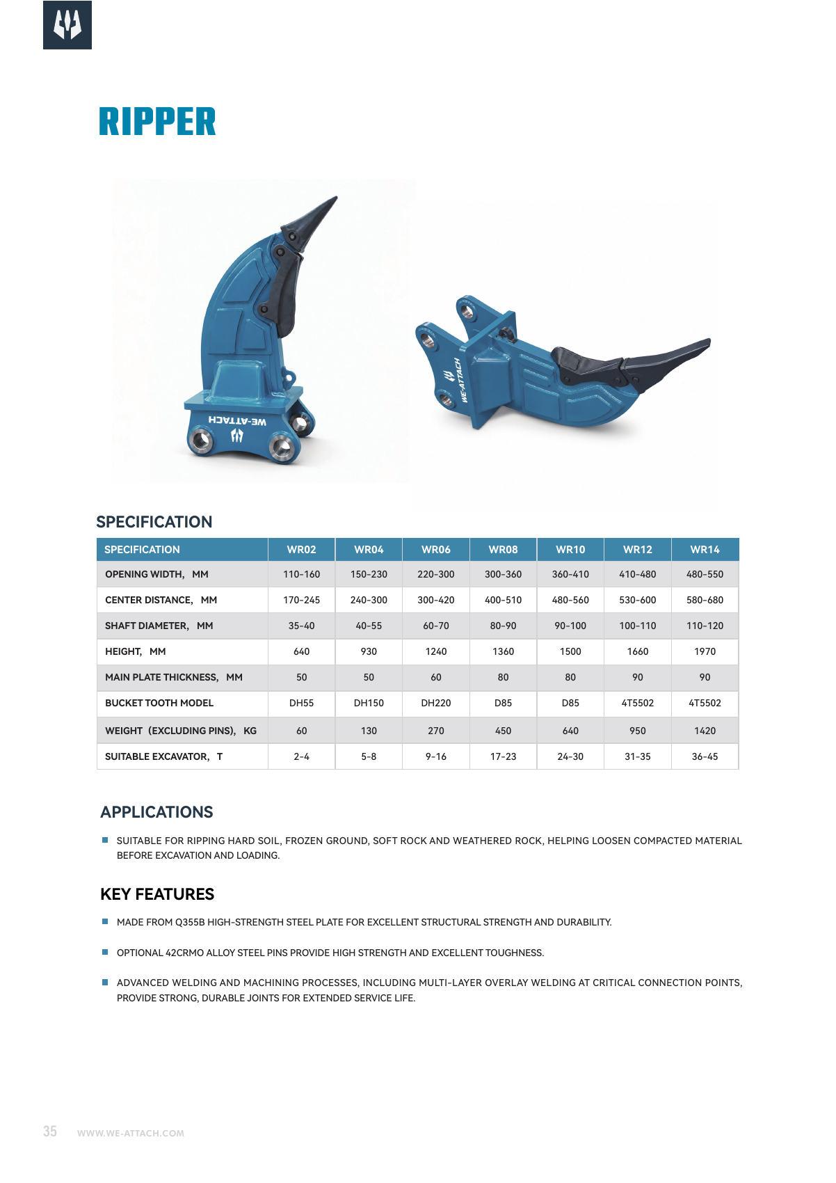
Catalogue specifications and source
| Field | Catalogue reference | Source physical page |
|---|---|---|
| Model | WR10 | P03 · p.36 ↗ |
| OPENING WIDTH, MM | 360-410 | P03 · p.36 ↗ |
| CENTER DISTANCE, MM | 480-560 | P03 · p.36 ↗ |
| SHAFT DIAMETER, MM | 90-100 | P03 · p.36 ↗ |
| HEIGHT, MM | 1500 | P03 · p.36 ↗ |
| MAIN PLATE THICKNESS, MM | 80 | P03 · p.36 ↗ |
| BUCKET TOOTH MODEL | D85 | P03 · p.36 ↗ |
| WEIGHT(EXCLUDING PINS), KG | 640 | P03 · p.36 ↗ |
| SUITABLE EXCAVATOR, T | 24-30 | P03 · p.36 ↗ |
Drawing letters such as A/B refer to the original drawing keys; verify dimensions and units with the current model drawing.
Purpose and task
WR10 is the ripper reference for loosening resistant ground before excavation. Loosen resistant ground or material with the WR single-shank excavator-ripper range.
How this helps your buying decision
Measure pin diameter, centres and inside width; compare tip reach and the single-shank envelope with the machine and proposed material. Compare WR10 with WR08 as separate source-listed configurations. For OPENING WIDTH, MM, the listed values are 360-410 (WR10) and 300-360 (WR08). For WEIGHT(EXCLUDING PINS), KG, the listed values are 640 (WR10) and 450 (WR08). Keep units, mounting position, circuit labels and document conditions with each value. Similar model numbers or overlapping carrier references do not prove fitment, interchangeability or a better result for your task.
Model and configuration
The model-specific source row states: OPENING WIDTH, MM: 360-410; CENTER DISTANCE, MM: 480-560; SHAFT DIAMETER, MM: 90-100; HEIGHT, MM: 1500; MAIN PLATE THICKNESS, MM: 80; BUCKET TOOTH MODEL: D85; WEIGHT(EXCLUDING PINS), KG: 640; SUITABLE EXCAVATOR, T: 24-30. Retain the printed units, dimension keys and applicable circuit or mounting labels; unknown drawing units require confirmation rather than conversion.
Machine and interface review
Measure pin diameter, centres and inside width; compare tip reach and the single-shank envelope with the machine and proposed material. Check mounting pins, centres, inside width, overall envelope and clearance through the intended movement against the actual assembly drawing. Catalogue carrier references are preliminary selection information, not machine-specific approval.
Installation, control and operating conditions
Review the mechanical connection, linkage, swept movement and retaining/locking details against the current installation drawing. No additional grapple or ripper hydraulic input is assigned from a different product family. This is a mechanical attachment. Source weight excludes pins; carrier reference and tooth code do not guarantee a material hardness or ripping production rate.
Structure and differences
The supplied product text describes side reinforcement and a replaceable tip/tooth; WR models have their own interface and geometry rows. This is a mechanical attachment. Source weight excludes pins; carrier reference and tooth code do not guarantee a material hardness or ripping production rate.
Application boundaries
A ripper is not a compactor. No production rate or material hardness capability follows from the carrier reference alone.
Manufacturing and quality responsibility
WE-ATTACH supports attachment selection, configuration requirements and coordinated supply through core manufacturing partners, with a warehouse and hillside testing site. Keep the actual manufacturer, ordered model and applicable scope with inspection, material or compliance records. A partner facility certificate or catalogue image is not model-specific product approval.
Documents, parts and operation
Use P03 physical PDF page 36 and the model-reference CSV linked on this page. Each exported parameter retains its source ID and physical page. Catalogue sketches, source images and selection tables are reference information; request the current mounting/connection drawing, operating and maintenance instructions and model-specific evidence for the actual ordered configuration.
Options and scope of supply
Specify the tooth/tip and retaining parts, shank, mounting pins and any wear/repair components; confirm tooth-reference compatibility. Have the quotation identify the attachment, mounting, controls/connections, included accessories and required parts individually. A pictured option, support frame or related tool is not automatically included.
Information to send with a WR10 enquiry
For WR10, send machine make/model and operating weight; mounting/linkage dimensions; available circuit and return information where applicable; material, work stage, access/reach and desired result; Material; tooth configuration; pin/centre/width; reach; current drawing and work arrangement. Include quantity, destination and any drawings/photos. State units and identify unknown values rather than substituting a similar machine or model.
Before confirming the order
Agree the complete model and suffix, actual machine, interfaces, operating conditions and scope of supply. Keep unresolved source descriptions and accepted drawing/document revisions with the quotation. Confirm inspection/document requirements, price, delivery, warranty and service scope for the actual order; no unverified term or performance commitment is added here.
Source and document traceability
Catalogue transcription for preliminary review. Confirm the applicable configuration and current approved revision before order.
- Excavator Attachment Catalogue ↗ · PDF physical page 36
Applications and working conditions
Selection and purchase guides
Questions before selection
What task does WR10 address?
WR10 is the ripper reference for loosening resistant ground before excavation. Loosen resistant ground or material with the WR single-shank excavator-ripper range.
Which information should accompany a WR10 enquiry?
For WR10, send machine make/model and operating weight; mounting/linkage dimensions; available circuit and return information where applicable; material, work stage, access/reach and desired result; Material; tooth configuration; pin/centre/width; reach; current drawing and work arrangement. Include quantity, destination and any drawings/photos. State units and identify unknown values rather than substituting a similar machine or model.
What must be checked before confirming this configuration?
A ripper is not a compactor. No production rate or material hardness capability follows from the carrier reference alone.
How should I compare WR10 with another configuration?
Compare WR10 with WR08 as separate source-listed configurations. For OPENING WIDTH, MM, the listed values are 360-410 (WR10) and 300-360 (WR08). For WEIGHT(EXCLUDING PINS), KG, the listed values are 640 (WR10) and 450 (WR08). Keep units, mounting position, circuit labels and document conditions with each value. Similar model numbers or overlapping carrier references do not prove fitment, interchangeability or a better result for your task. This is a mechanical attachment. Source weight excludes pins; carrier reference and tooth code do not guarantee a material hardness or ripping production rate.
What installation and operating information is needed for WR10?
Measure pin diameter, centres and inside width; compare tip reach and the single-shank envelope with the machine and proposed material. Review the mechanical connection, linkage, swept movement and retaining/locking details against the current installation drawing. No additional grapple or ripper hydraulic input is assigned from a different product family.
Where can I check the source and current documents for WR10?
Use P03 physical PDF page 36 and the model-reference CSV linked on this page. Each exported parameter retains its source ID and physical page. Catalogue sketches, source images and selection tables are reference information; request the current mounting/connection drawing, operating and maintenance instructions and model-specific evidence for the actual ordered configuration.
Which parts and options should the WR10 quotation identify?
Specify the tooth/tip and retaining parts, shank, mounting pins and any wear/repair components; confirm tooth-reference compatibility. Confirm the exact configuration and each included item rather than using a family illustration as a packing list.
Related model references
Product type and related work stages
Heavy-duty Hydraulic Breakers
Review heavy-duty WHB breaker models for the machine capacity and proposed breaking conditions.
11 listed modelsView type, details & selection →Crushing Buckets
Reduce suitable material at the excavator with the WBC crushing-bucket range.
2 listed modelsView type, details & selection →Drum Cutter 01
Cut or profile suitable material with the supplied transverse drum-cutter form.
Specify your configurationView type, details & selection →Drum Cutter 02
Review the second supplied drum-cutter configuration for the proposed cutting task and carrier.
Specify your configurationView type, details & selection →Heavy-duty Rock Buckets
Excavate rock-bearing material with the supplied reinforced rock-bucket form.
Specify your configurationView type, details & selection →