
FROM AN IDEA TO A REQUIREMENT
What to specify for this attachment
Use these decisions to turn the work requirement into a model and configuration enquiry.
| Decision | Why it matters | Information to provide |
|---|---|---|
| Work stage and material | Steel cutting, primary concrete processing and secondary reduction are not interchangeable. | Material, section/reinforcement and the proposed work sequence. |
| Jaw and mounting arrangement | Opening and tool position affect access and the working envelope. | Section/block size, mounting position and required reach/clearance. |
| Hydraulics and positioning | Working and rotation requirements belong to the exact head arrangement. | Machine, flow, pressure and the required rotation circuit. |
| Wear parts and documents | Blade/tooth arrangement and technical revision stay with the configuration. | Full model/suffix, blade/teeth information and current drawing requirements. |
View the supplied catalogue drawing and original technical page
Supplier-provided catalogue reference · P03 physical page 17. Check the exact model header, configuration and source version. This excerpt is not a substitute for the current approved installation drawing or a model-specific test report.
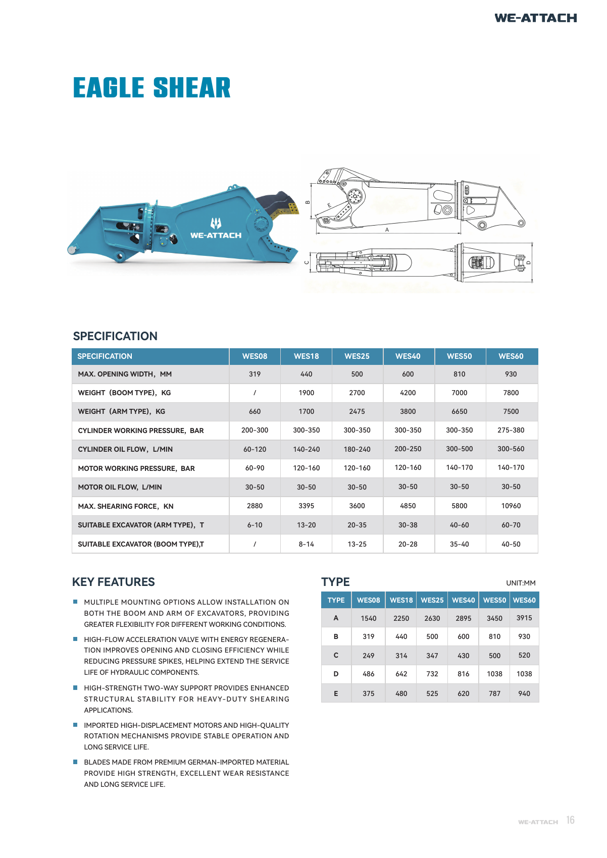
Catalogue specifications and source
| Field | Catalogue reference | Source physical page |
|---|---|---|
| Model | WES40 | P03 · p.17 ↗ |
| A | 2895 | P03 · p.17 ↗ |
| B | 600 | P03 · p.17 ↗ |
| C | 430 | P03 · p.17 ↗ |
| D | 816 | P03 · p.17 ↗ |
| E | 620 | P03 · p.17 ↗ |
| MAX. OPENING WIDTH, MM | 600 | P03 · p.17 ↗ |
| WEIGHT (BOOM TYPE), KG | 4200 | P03 · p.17 ↗ |
| WEIGHT (ARM TYPE), KG | 3800 | P03 · p.17 ↗ |
| CYLINDER WORKING PRESSURE, BAR | 300-350 | P03 · p.17 ↗ |
| CYLINDER OIL FLOW, L/MIN | 200-250 | P03 · p.17 ↗ |
| MOTOR WORKING PRESSURE, BAR | 120-160 | P03 · p.17 ↗ |
| MOTOR OIL FLOW, L/MIN | 30-50 | P03 · p.17 ↗ |
| MAX. SHEARING FORCE, KN | 4850 | P03 · p.17 ↗ |
| SUITABLE EXCAVATOR (ARM TYPE), T | 30-38 | P03 · p.17 ↗ |
| SUITABLE EXCAVATOR (BOOM TYPE), T | 20-28 | P03 · p.17 ↗ |
Drawing letters such as A/B refer to the original drawing keys; verify dimensions and units with the current model drawing.
Purpose and task
WES40 is the eagle shear reference for metal section cutting. Cut metal with the WES eagle-shear arrangement, selecting the jaw geometry for the proposed section.
How this helps your buying decision
Choose boom or arm mounting first: the source records different mass and carrier references for those arrangements. Check the jaw envelope at the required reach. Compare WES40 with WES25 as separate source-listed configurations. For CYLINDER OIL FLOW, L/MIN, the listed values are 200-250 (WES40) and 180-240 (WES25). For MOTOR OIL FLOW, L/MIN, the listed values are 30-50 (WES40) and 30-50 (WES25). Keep units, mounting position, circuit labels and document conditions with each value. Similar model numbers or overlapping carrier references do not prove fitment, interchangeability or a better result for your task.
Model and configuration
The model-specific source row states: A: 2895; B: 600; C: 430; D: 816; E: 620; MAX. OPENING WIDTH, MM: 600; WEIGHT (BOOM TYPE), KG: 4200; WEIGHT (ARM TYPE), KG: 3800; CYLINDER WORKING PRESSURE, BAR: 300-350; CYLINDER OIL FLOW, L/MIN: 200-250; MOTOR WORKING PRESSURE, BAR: 120-160; MOTOR OIL FLOW, L/MIN: 30-50; MAX. SHEARING FORCE, KN: 4850; SUITABLE EXCAVATOR (ARM TYPE), T: 30-38; SUITABLE EXCAVATOR (BOOM TYPE), T: 20-28. Retain the printed units, dimension keys and applicable circuit or mounting labels; unknown drawing units require confirmation rather than conversion.
Machine and interface review
Choose boom or arm mounting first: the source records different mass and carrier references for those arrangements. Check the jaw envelope at the required reach. Check mounting pins, centres, inside width, overall envelope and clearance through the intended movement against the actual assembly drawing. Catalogue carrier references are preliminary selection information, not machine-specific approval.
Installation, control and operating conditions
The source lists CYLINDER WORKING PRESSURE, BAR: 300-350; CYLINDER OIL FLOW, L/MIN: 200-250; MOTOR WORKING PRESSURE, BAR: 120-160; MOTOR OIL FLOW, L/MIN: 30-50. Check the actual machine flow/pressure at the intended settings, control/valve arrangement, hose/coupling dimensions, return/back-pressure and any case-drain requirement against the current hydraulic drawing. Separate catalogue ranges or maxima do not establish one approved simultaneous running point. Keep maximum shearing force distinct from opening width; the force figure alone does not define a cuttable steel thickness or section grade.
Structure and differences
The supplied material discusses cutting arms/blades, rotation equipment and alternative mounting heads. The readable dimension table is kept separate from overlapping source annotations. Keep maximum shearing force distinct from opening width; the force figure alone does not define a cuttable steel thickness or section grade.
Application boundaries
No underwater depth, “first” claim, comparative wear percentage or unsupported force value is inferred. Mounting reach and machine stability need project review.
Manufacturing and quality responsibility
WE-ATTACH supports attachment selection, configuration requirements and coordinated supply through core manufacturing partners, with a warehouse and hillside testing site. Keep the actual manufacturer, ordered model and applicable scope with inspection, material or compliance records. A partner facility certificate or catalogue image is not model-specific product approval.
Documents, parts and operation
Use P03 physical PDF page 17 and the model-reference CSV linked on this page. Each exported parameter retains its source ID and physical page. Catalogue sketches, source images and selection tables are reference information; request the current mounting/connection drawing, operating and maintenance instructions and model-specific evidence for the actual ordered configuration.
Options and scope of supply
Specify the cutting blade, mounting head, blade adjustment and applicable parts identification. Have the quotation identify the attachment, mounting, controls/connections, included accessories and required parts individually. A pictured option, support frame or related tool is not automatically included.
Information to send with a WES40 enquiry
For WES40, send machine make/model and operating weight; mounting/linkage dimensions; available circuit and return information where applicable; material, work stage, access/reach and desired result; Section/material; required opening; mounting head/position; reach; rotation/cylinder circuits and current drawing. Include quantity, destination and any drawings/photos. State units and identify unknown values rather than substituting a similar machine or model.
Before confirming the order
Agree the complete model and suffix, actual machine, interfaces, operating conditions and scope of supply. Keep unresolved source descriptions and accepted drawing/document revisions with the quotation. Confirm inspection/document requirements, price, delivery, warranty and service scope for the actual order; no unverified term or performance commitment is added here.
Source and document traceability
Catalogue transcription for preliminary review. Confirm the applicable configuration and current approved revision before order.
- Excavator Attachment Catalogue ↗ · PDF physical page 17
Applications and working conditions
Selection and purchase guides
Questions before selection
What task does WES40 address?
WES40 is the eagle shear reference for metal section cutting. Cut metal with the WES eagle-shear arrangement, selecting the jaw geometry for the proposed section.
Which information should accompany a WES40 enquiry?
For WES40, send machine make/model and operating weight; mounting/linkage dimensions; available circuit and return information where applicable; material, work stage, access/reach and desired result; Section/material; required opening; mounting head/position; reach; rotation/cylinder circuits and current drawing. Include quantity, destination and any drawings/photos. State units and identify unknown values rather than substituting a similar machine or model.
What must be checked before confirming this configuration?
No underwater depth, “first” claim, comparative wear percentage or unsupported force value is inferred. Mounting reach and machine stability need project review.
How should I compare WES40 with another configuration?
Compare WES40 with WES25 as separate source-listed configurations. For CYLINDER OIL FLOW, L/MIN, the listed values are 200-250 (WES40) and 180-240 (WES25). For MOTOR OIL FLOW, L/MIN, the listed values are 30-50 (WES40) and 30-50 (WES25). Keep units, mounting position, circuit labels and document conditions with each value. Similar model numbers or overlapping carrier references do not prove fitment, interchangeability or a better result for your task. Keep maximum shearing force distinct from opening width; the force figure alone does not define a cuttable steel thickness or section grade.
What installation and operating information is needed for WES40?
Choose boom or arm mounting first: the source records different mass and carrier references for those arrangements. Check the jaw envelope at the required reach. The source lists CYLINDER WORKING PRESSURE, BAR: 300-350; CYLINDER OIL FLOW, L/MIN: 200-250; MOTOR WORKING PRESSURE, BAR: 120-160; MOTOR OIL FLOW, L/MIN: 30-50. Check the actual machine flow/pressure at the intended settings, control/valve arrangement, hose/coupling dimensions, return/back-pressure and any case-drain requirement against the current hydraulic drawing. Separate catalogue ranges or maxima do not establish one approved simultaneous running point.
Where can I check the source and current documents for WES40?
Use P03 physical PDF page 17 and the model-reference CSV linked on this page. Each exported parameter retains its source ID and physical page. Catalogue sketches, source images and selection tables are reference information; request the current mounting/connection drawing, operating and maintenance instructions and model-specific evidence for the actual ordered configuration.
Which parts and options should the WES40 quotation identify?
Specify the cutting blade, mounting head, blade adjustment and applicable parts identification. Confirm the exact configuration and each included item rather than using a family illustration as a packing list.
Related model references
Product type and related work stages
Hydraulic Steel Shears
Cut steel sections and prepare metal for handling with the WHS hydraulic steel-shear range.
5 listed modelsView type, details & selection →Car Dismantling Shears
Grip and cut vehicle components during controlled dismantling with the WVS shear range.
2 listed modelsView type, details & selection →