
FROM AN IDEA TO A REQUIREMENT
What to specify for this attachment
Use these decisions to turn the work requirement into a model and configuration enquiry.
| Decision | Why it matters | Information to provide |
|---|---|---|
| Hole and ground | The same nominal hole can need different tooling in different ground. | Diameter, depth, ground description and the required result. |
| Drive and shaft | The drive output and the tooling connection belong in one configuration. | Machine flow/pressure, output shaft and mounting information. |
| Auger string | Drive, auger, extension, teeth and pilot are separate specification items. | The intended tooling, any extension and wear-part identification. |
| Reference performance | Source depth/torque values retain their conditions and version. | The exact model, source page and any unresolved data difference. |
View the supplied catalogue drawing and original technical page
Supplier-provided catalogue reference · P03 physical page 4. Check the exact model header, configuration and source version. This excerpt is not a substitute for the current approved installation drawing or a model-specific test report.
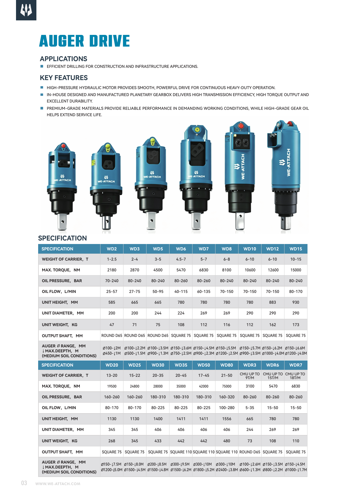
Catalogue specifications and source
| Field | Catalogue reference | Source physical page |
|---|---|---|
| Model | WD6 | P03 · p.4 ↗ |
| WEIGHT OF CARRIER,T | 4.5-7 | P03 · p.4 ↗ |
| MAX. TORQUE, NM | 5470 | P03 · p.4 ↗ |
| OIL FLOW,L/MIN | 40-115 | P03 · p.4 ↗ |
| UNIT HEIGHT, MM | 780 | P03 · p.4 ↗ |
| UNIT WEIGHT, KG | 108 | P03 · p.4 ↗ |
| OUTPUT SHAFT, MM | SQUARE 75 | P03 · p.4 ↗ |
| MAX. OUTPUT SPEED, RPM (P02 reference) | 78 | P02 · p.8 ↗ |
Drawing letters such as A/B refer to the original drawing keys; verify dimensions and units with the current model drawing.
Purpose and task
P02 physical page 8 identifies WD6 in its MD auger-drive group. The drive turns a separately selected auger for hole drilling; the hitch, ground tool and any extension remain part of the proposed configuration.
How this helps your buying decision
Confirm the pressure description, body clearance and lower auger-diameter boundary before choosing the mounted assembly. Compare WD6 with WD7 as separate source-listed assemblies. The catalogue torque references are 5470 Nm and 6830 Nm respectively. Their source-listed flow references are 40-115 L/min and 60-135 L/min. Check the carrier definition, mounting, shaft and hydraulic conditions for each option; a higher model number is not an interchangeability approval.
Compare WD6 with WD5 as separate source-listed configurations. For MAX. TORQUE, NM, the listed values are 5470 (WD6) and 4500 (WD5). For OIL FLOW,L/MIN, the listed values are 40-115 (WD6) and 50-95 (WD5). Keep units, mounting position, circuit labels and document conditions with each value. Similar model numbers or overlapping carrier references do not prove fitment, interchangeability or a better result for your task.
Model and configuration
Carrier reference, t: 4.5-7 (P03 physical page 4); Maximum torque, Nm: 5470 (P03 physical page 4); Hydraulic flow, L/min: 40-115 (P03 physical page 4); Unit height, mm: 780 (P03 physical page 4); Unit weight, kg: 108 (P03 physical page 4); Output shaft, mm: SQUARE 75 (P03 physical page 4). P02 physical page 8 also lists 78 rpm as a maximum output-speed reference. Catalogue values describe the source record, not a confirmed simultaneous running point or a fully installed package.
Machine and interface review
Check the actual machine model, mounting-pin sizes, centres, inside width, installation space and motion clearance. P02 physical page 8 illustrates mounting options; the pictures do not define which hitch, frame or hydraulic connections are included.
Hydraulic, control and installation conditions
Use the source-version comparison for the unresolved pressure description before matching WD6 to a machine circuit. Identify the proposed control/valve arrangement, hoses, couplings, return and back-pressure requirements against the current hydraulic drawing. Separate catalogue maxima do not establish a continuous-duty point or a complete speed/torque curve.
Structure and differences
The supplied auger-drive family description uses a hydraulic motor and planetary gearbox arrangement. For WD6, check the documented output shaft, drive dimensions and mounted tool package; a family photograph is not evidence of the exact supplied motor, hitch or auger.
Application boundaries
The page retains the unresolved source descriptions, including Drive diameter: P02 p.8: 269 mm versus P03 p.4: 224 mm. Ask which drawing and source revision define the offered assembly. Do not select a convenient number from different versions to create a new operating point.
Manufacturing and quality responsibility
WE-ATTACH supports attachment selection, configuration requirements and coordinated supply through core manufacturing partners, with a warehouse and hillside testing site. Request the actual manufacturer, ordered assembly and scope on inspection or compliance records; a partner facility certificate does not certify every listed model.
Documents, parts and operation
Check the WD6 column on P03 physical PDF page 4 and P02 physical page 8, P02 physical page 25. The model-specific links retain the original physical page numbers. The specification CSV identifies the source for each field; a separate version-comparison CSV is available where source differences exist. These are catalogue/selection references. Current installation and hydraulic drawings, operating instructions and a model-specific performance curve must be requested and checked for the actual ordered configuration.
Ground tools and scope of supply
The drive lists a 75 mm square output shaft. P02 physical page 25 supplies related hub, auger and wear-part references. Confirm the complete hub/retaining arrangement, flight length, teeth/pilot, any extension and the ground before choosing the tool. Have the quotation list the drive, hitch/frame, auger, extension, connections and wear parts separately.
Information to send with a WD6 enquiry
For WD6, send the carrier make/model and the meaning of its rated reference; machine/mounting dimensions; hydraulic flow, pressure and return information; hole diameter and depth; ground description; the required auger/extension; quantity and destination. Include units, available drawings and any open source-version questions.
Before confirming the order
Agree the exact WD6 configuration, source/drawing revision, carrier interface, hydraulic conditions and included ground tools. Resolve open parameter versions before converting a catalogue reference into an order requirement. Price, delivery, warranty scope and any required documentation remain quotation-specific.
Source and document traceability
Catalogue transcription for preliminary review. Confirm the applicable configuration and current approved revision before order.
- Excavator Attachment Catalogue ↗ · PDF physical page 4
- Auger Drive Selection Guide ↗ · PDF physical page 8
- Auger Drive Selection Guide ↗ · PDF physical page 25
Applications and working conditions
Selection and purchase guides
Questions before selection
What task does WD6 address?
P02 physical page 8 identifies WD6 in its MD auger-drive group. The drive turns a separately selected auger for hole drilling; the hitch, ground tool and any extension remain part of the proposed configuration.
Which information should accompany a WD6 enquiry?
For WD6, send the carrier make/model and the meaning of its rated reference; machine/mounting dimensions; hydraulic flow, pressure and return information; hole diameter and depth; ground description; the required auger/extension; quantity and destination. Include units, available drawings and any open source-version questions.
What must be checked before confirming this configuration?
The page retains the unresolved source descriptions, including Drive diameter: P02 p.8: 269 mm versus P03 p.4: 224 mm. Ask which drawing and source revision define the offered assembly. Do not select a convenient number from different versions to create a new operating point.
Which hydraulic and control conditions matter for WD6?
Use the source-version comparison for the unresolved pressure description before matching WD6 to a machine circuit. Identify the proposed control/valve arrangement, hoses, couplings, return and back-pressure requirements against the current hydraulic drawing. Separate catalogue maxima do not establish a continuous-duty point or a complete speed/torque curve.
Does the 75 mm square shaft prove that my auger will fit?
The drive lists a 75 mm square output shaft. P02 physical page 25 supplies related hub, auger and wear-part references. Confirm the complete hub/retaining arrangement, flight length, teeth/pilot, any extension and the ground before choosing the tool.
How should I compare WD6 with WD7?
Compare WD6 with WD7 as separate source-listed assemblies. The catalogue torque references are 5470 Nm and 6830 Nm respectively. Their source-listed flow references are 40-115 L/min and 60-135 L/min. Check the carrier definition, mounting, shaft and hydraulic conditions for each option; a higher model number is not an interchangeability approval.
Which source documents and items should accompany a WD6 quotation?
Check the WD6 column on P03 physical PDF page 4 and P02 physical page 8, P02 physical page 25. The model-specific links retain the original physical page numbers. The specification CSV identifies the source for each field; a separate version-comparison CSV is available where source differences exist. These are catalogue/selection references. Current installation and hydraulic drawings, operating instructions and a model-specific performance curve must be requested and checked for the actual ordered configuration. Confirm which mounting, ground tool and connections are included in the quotation.
Related model references
Parameter versions requiring confirmation
These source descriptions are shown side by side. They have not been merged into one approved specification; unaffected catalogue fields are retained above.
| Field | Source description A | Source description B |
|---|---|---|
| Drive diameter | P02 p.8: 269 mm | P03 p.4: 224 mm |
| Pressure descriptions | P02 p.8: maximum 240 bar | P03 p.4: range 80–260 bar |
| UNIT DIAMETER, MM | P02 p.8: 269 mm | P03 p.4: 224 |
| OIL PRESSURE, BAR | P02 p.8: 240 bar (maximum) | P03 p.4: 80-260 |
| Medium-ground reference depth at diameter 750 mm | P02 p.8: 2.7 m | P03 p.4: 2.5 m |
| Lower auger diameter reference | P02 p.8 heading: 100 mm | P02 p.8 depth table / P03 p.4: first reference is 150 mm |
Product type and related work stages
Vibratory Pile Drivers
Grip and vibrate the proposed pile section with the WTV excavator-mounted pile-driver range.
4 listed modelsView type, details & selection →Augers, Extensions & Ground Tools
Match augers, extensions and replaceable ground tools to the drive, hole and ground conditions.
Specify your configurationView type, details & selection →